COVNA Products
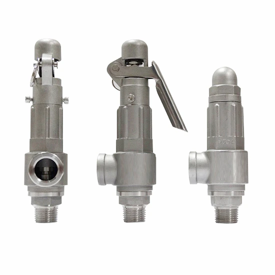
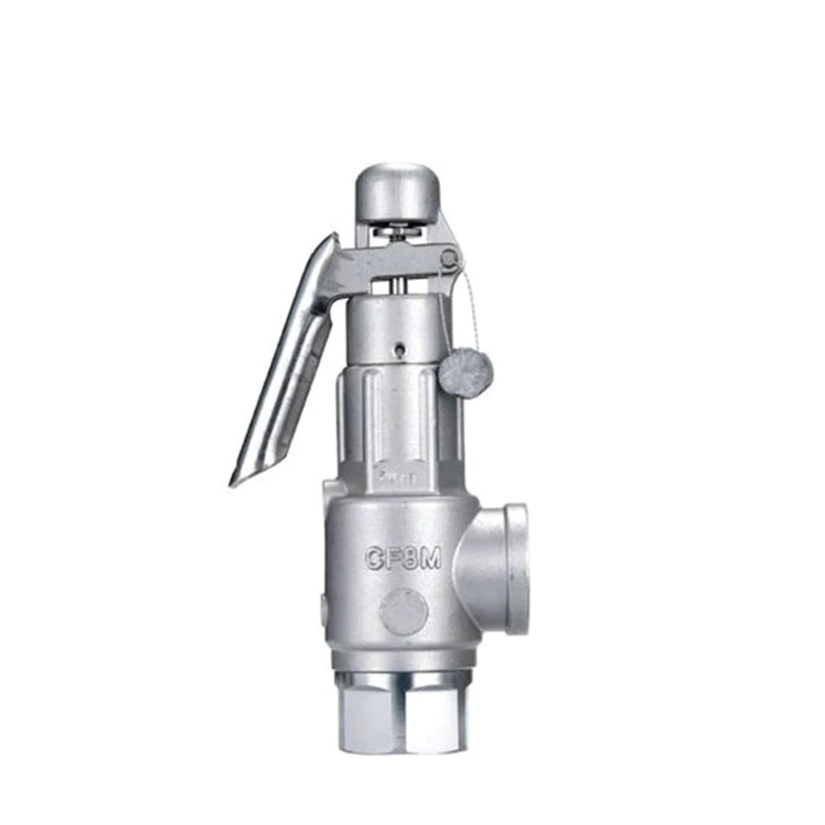
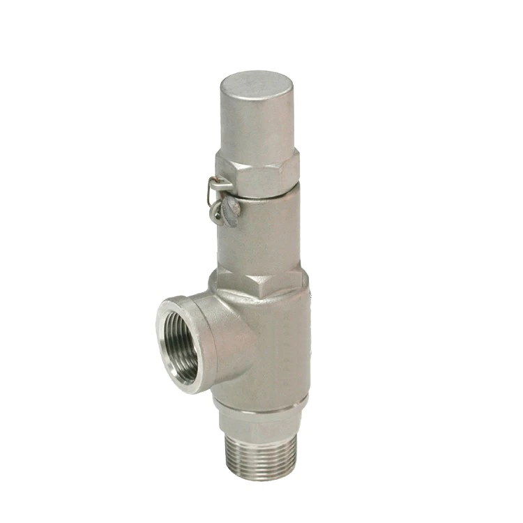
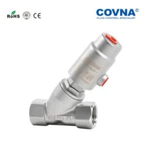
Stainless Steel Threaded Full-Lift Safety Valve
The stainless steel threaded full-lift safety valve is a full-lift safety pressure relief device designed specifically for overpressure protection in industrial pipelines and equipment. The valve body is constructed of high-quality stainless steel, precision-machined and heat-treated to provide excellent corrosion resistance and mechanical strength. The disc instantly opens fully when the preset pressure is reached, enabling rapid discharge and ensuring safe and stable system operation. This valve is widely suitable for pressure protection applications involving steam, air, liquids, and various non-aggressive media.
Main Features
- Fast Full Opening: Upon overpressure, the disc immediately opens fully, providing high discharge efficiency.
- Threaded Connection: Standard imperial threaded connections are used for simple installation and space-saving design.
- High Corrosion Resistance: Made of 304/316 stainless steel, suitable for a variety of operating environments.
- Precision Adjustment: Equipped with a lock nut, the opening pressure can be precisely adjusted on-site.
- Sealing Performance: The valve seat and disc fit tightly together, ensuring zero leakage.
- Easy Maintenance: Compact structure allows for quick disassembly and maintenance.
Technical Specifications
| Parameter | Specification Range |
|---|---|
| Diameter Range | 1/2" to 4" |
| Nominal Pressure | PN 16 to PN 260 |
| Medium Temperature | -29 °C to +425 °C |
| Applicable Media | Steam, air, water, oil, etc. |
| Body Material | 304 / 316 stainless steel |
| Connection Type | British thread (ISO 7/1 BSPT) |
Application Scenarios
- Boiler and steam piping: prevents pipe rupture from overpressure
- Pressure vessels: protects reactors, heat exchangers, and storage tanks
- Chemical and petrochemical: maintains safety in corrosive media systems
- Pharmaceutical and food processing: meets hygienic standards and easy cleaning
- Power generation and paper mills: ensures reliable operation under high temperature
Installation and Selection Guide
- Determine the system’s maximum allowable working pressure and select a valve with an opening pressure 10%–20% above that value.
- Install the safety valve as close as possible to the equipment’s discharge point, in a vertical or near-vertical orientation.
- Provide a straight inlet pipe run of at least 5–10 times the valve diameter to avoid flow disturbances.
- Regularly test and calibrate the set pressure to maintain sensitivity and sealing performance.
- Install discharge piping to direct relieved media safely to a designated location.
Frequently Asked Questions
How do I determine the correct opening pressure? Measure the system’s highest working pressure and add a safety margin of 10%–20% when selecting the valve.
What if the process media contains impurities? Install a strainer upstream of the valve and perform routine cleaning to prevent clogging.
Does installation orientation affect performance? Vertical installation provides optimal relief flow. If the valve must be angled, recalibrate flow performance accordingly.
For personalized selection assistance or technical support, please contact our customer service team or submit an online inquiry. We will provide you with a dedicated, one-on-one solution.
The actuator on my automated valve operates, but the valve won’t turn. Why?
Most likely the valve stem or actuator coupling is broken.
Why doesn’t my valve open or close completely when the actuator operates it?
The electric actuator limit switches or the pneumatic actuator position stops are not correctly adjusted.
When I energize the solenoid on my pneumatic actuated valve, the valve won’t turn. How come?
Probably because there is no air pressure to the solenoid or dirt has jammed it. Also, debris might be trapped inside the valve. Or, the air pressure is not sufficient to operate the actuator. Remember: measure air pressure at the actuator, not at the compressor.
Can I buy an actuator from one manufacturer and mount it to a valve from another manufacturer?
Maybe. First, be sure that the actuator torque output is sufficient to turn the valve reliably. Second, you will have to fabricate a custom mounting bracket and coupling to connect the actuator to the valve.
What happens if I lose power to my electric actuator in the middle of an actuation cycle?
The valve will stop somewhere between full open and close. When power is reapplied to the original circuit, the actuator will complete the cycle.
I ordered a fail open pneumatic actuated valve by mistake. I needed a fail closed one. What can I do?
To make the change just remove the actuator from the valve and turn it, or the valve stem, 90 degrees and remount the actuator.
I’ve installed my automated valve in the line, but now I don’t know if the valve is in the open or closed position. How can I find out?
Remove the actuator from the valve and check the valve stem. Most ball valves have stem flats at right angles to the flow when the valve is in the off position. On butterfly valves check the stem flow arrow marking.
Do I have to have the solenoid valve that controls the air supply to my pneumatic actuator mounted right on the actuator?
Remove the actuator from the valve and check the valve stem. Most ball valves have stem flats at right angles to the flow when the valve is in the off position. On butterfly valves check the stem flow arrow marking.
How do I wire up my electric actuator?
Check the electric wiring schematic that came with the actuator for the correct hookup. Sometimes a copy is inside the actuator cover. If it is missing, don’t guess about the connections. Call the manufacturer for a schematic.
I’ve just installed an electric actuated valve and when I power it, it turns the valve 360 degrees and won’t shut off. What’s wrong?
The actuator is wired incorrectly (check the schematic accompanying the actuator), or the external control switch is not the correct type for the actuator.
My electric actuators cycle time is way too fast, can I slow it down?
Not unless you bought it with an optional speed control.
I just replaced a solenoid valve with an electric actuated valve and it won’t work. Why?
Actuators and solenoid valves require different types of electrical control switches. SPDT for actuators, SPST for solenoids. Check the actuator wiring schematic for the correct wiring and switch type.