
## Introduction to Solenoid Valve Technology
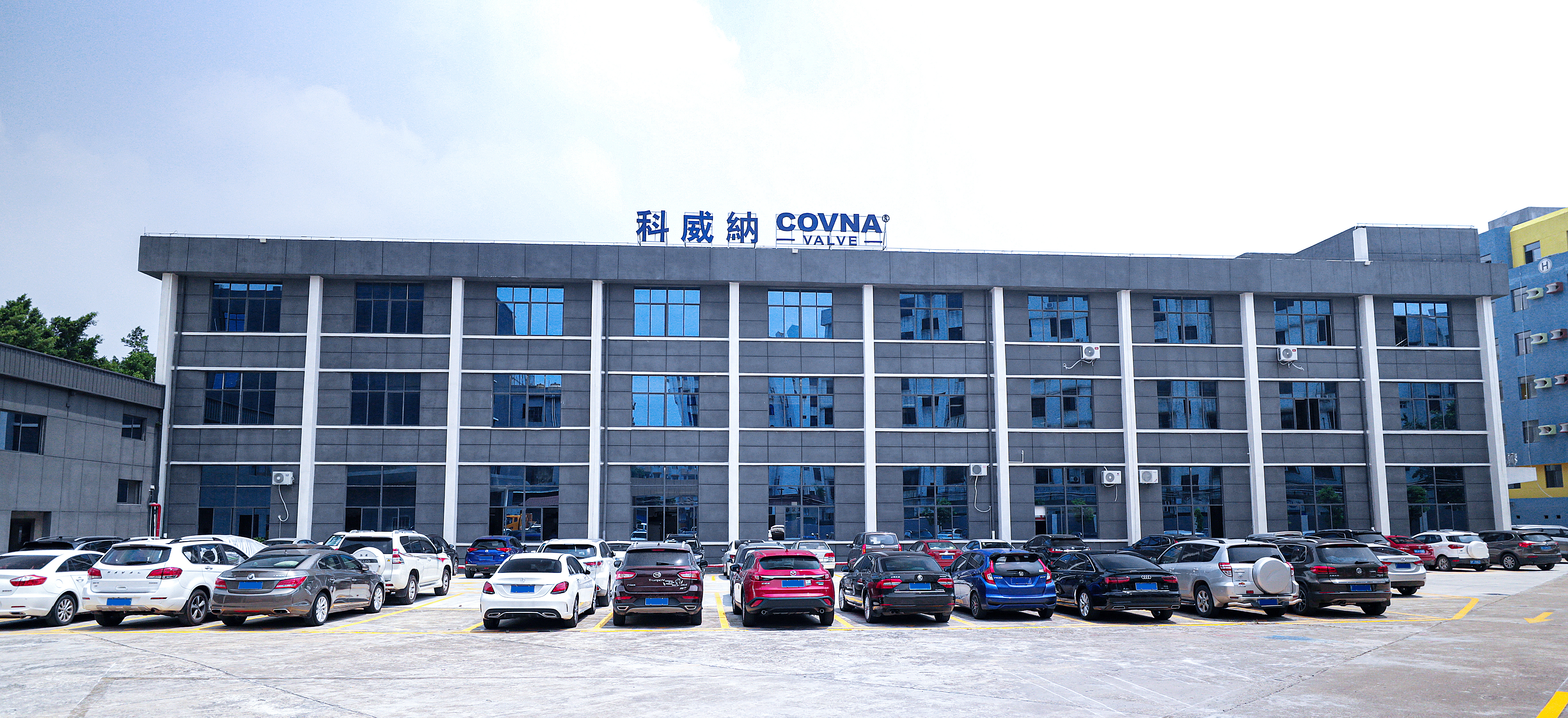
In the complex world of industrial automation and fluid control systems, solenoid valves serve as critical components that enable precise, reliable control of liquids and gases across countless applications. As a world-leading valve manufacturer with over **17 years of expertise**, **COVNA GROUP CO., LTD** has designed and supplied solenoid valves to more than **5,000 industrial applications** worldwide, establishing a reputation for German-inspired precision engineering and dependable performance.
Understanding **how a solenoid valve works** is essential for engineers, procurement professionals, and technical decision-makers who need to specify, install, or maintain these vital components. This comprehensive engineering guide explores the fundamental physics behind solenoid valve operation, examines construction details, reviews various valve types, and provides practical application guidance based on real-world industrial experience.
**Table 1: Common Solenoid Valve Applications by Industry**
| Industry Sector | Primary Applications | Typical Valve Specifications | Key Requirements |
|-----------------|---------------------|------------------------------|------------------|
| Water Treatment | Filtration, backwash, chemical dosing | Brass, 2-way NC, 24VDC | Corrosion resistance, long cycle life |
| Chemical Processing | Reactor control, transfer lines | 316 SS, PTFE seals, 220VAC | Chemical compatibility, high temperature |
| Food & Beverage | CIP systems, filling machines | 316L SS, sanitary fittings | FDA compliance, easy cleaning |
| Oil & Gas | Wellhead control, pipeline isolation | Explosion-proof, high pressure | Safety certifications, reliability |
| HVAC Systems | Chiller control, zone dampers | 24VAC, 2-way or 3-way | Quiet operation, energy efficiency |
| Pharmaceutical | Purified water, WFI systems | 316L SS, electropolished | USP compliance, validation docs |
## What Is a Solenoid Valve?
A **solenoid valve** is an electromechanically operated valve that controls the flow of liquids or gases through a system by using an electromagnetic solenoid to actuate a valve mechanism. Unlike manually operated valves that require physical force to open or close, solenoid valves can be remotely controlled through electrical signals, enabling automation, precise timing, and integration with control systems.
The fundamental principle behind solenoid valve operation dates back to the early 19th century when scientists first discovered the relationship between electricity and magnetism. However, practical industrial solenoid valves emerged in the mid-20th century as manufacturing capabilities advanced and industrial automation requirements grew. Today's solenoid valves incorporate sophisticated materials, precise manufacturing tolerances, and specialized seal technologies that enable reliable operation across extreme temperatures, pressures, and chemical environments.
**Table 2: Solenoid Valve vs Other Valve Types Comparison**
| Valve Type | Actuation Method | Response Time | Remote Control | Typical Applications | Cost Range |
|------------|-----------------|---------------|----------------|---------------------|------------|
| Solenoid Valve | Electromagnetic | 20-100 ms | Yes, electrical signal | Automation, process control | $20-$500 |
| Manual Valve | Handwheel/lever | Human speed | No | Isolation, maintenance | $10-$200 |
| Pneumatic Valve | Air pressure | 50-200 ms | Yes, air signal | Hazardous environments | $50-$800 |
| Electric Motor Valve | Motor drive | 5-30 seconds | Yes, electrical signal | Large valves, precise positioning | $200-$5000 |
| Hydraulic Valve | Oil pressure | 20-100 ms | Yes, hydraulic signal | High force applications | $100-$2000 |
## How Does a Solenoid Valve Work? The Physics
Understanding **how a solenoid valve works** requires examining the fundamental electromagnetic principles that enable these devices to convert electrical energy into mechanical motion. The operation involves three key physical phenomena: electromagnetic induction, magnetic force generation, and spring mechanics.
### The Electromagnetic Principle
When an electrical current flows through a wire, it creates a circular magnetic field around that wire according to the right-hand rule—if you point your right thumb in the direction of current flow, your fingers curl in the direction of the magnetic field. A **solenoid** takes advantage of this principle by coiling the wire many times, typically hundreds or thousands of turns, creating a concentrated magnetic field along the axis of the coil.
The strength of this electromagnetic field depends on several factors that valve manufacturers must carefully engineer:
**Table 3: Electromagnetic Force Calculation Factors**
| Factor | Symbol | Unit | Effect on Force | Typical Valve Range |
|--------|--------|------|-----------------|---------------------|
| Number of coil turns | N | turns | Directly proportional | 500-5000 turns |
| Current through coil | I | Amperes | Directly proportional | 0.1-2.0 A |
| Coil voltage | V | Volts | Determines current | 12V, 24V, 110V, 220V |
| Magnetic path efficiency | μ | unitless | Affected by materials | 0.6-0.95 |
| Plunger stroke | s | mm | Inverse relationship | 2-20 mm |
| Core material permeability | μr | unitless | Higher = stronger field | 2000-10000 |
### Coil Energization Process
When the solenoid valve's electrical circuit is closed (energized), current flows through the coil according to Ohm's Law: I = V/R, where V is the applied voltage and R is the coil resistance. The current doesn't instantly reach its maximum value due to the coil's inductance—a property that opposes changes in current flow.
The time constant τ (tau) of an RL circuit is calculated as τ = L/R, where L is inductance in Henries and R is resistance in Ohms. For most industrial solenoid valves:
- \n
- Typical inductance: 0.5 - 5.0 H
- Typical resistance: 50 - 500 Ω
- Resulting time constant: 2 - 50 milliseconds
\n
\n
\n
\n\n
Practical implication: The magnetic field (and consequently the valve response) reaches approximately 63% of maximum strength in one time constant, 95% in three time constants, and 99% in five time constants. For a valve with τ = 10ms, full response occurs in approximately 50ms.
\n\n
| Voltage Type | Typical Voltage | Power (AC) | Power (DC) | Common Applications |
|---|---|---|---|---|
|
Low DC |
12VDC / 24VDC |
N/A | 3-15W | Mobile equipment, vehicles, battery systems |
| Standard DC | 24VDC / 48VDC | N/A | 5-25W | Industrial automation, PLCs |
| Control AC | 24VAC / 110VAC | 8-20VA | N/A | HVAC, building automation |
| Mains AC | 220VAC / 240VAC | 10-30VA | N/A | General industrial, commercial |
\n\n
Conclusion
\n\n
Understanding how a solenoid valve works is fundamental knowledge for anyone involved in fluid control system design and maintenance. These electromechanical devices serve as the critical interface between electrical control systems and fluid handling processes.
\n\n
COVNA GROUP CO., LTD brings over 17 years of specialized experience in solenoid valve design and manufacturing. With ISO 9001, CE, and RoHS certifications, COVNA provides reliable valve application solutions with rapid response to customer requirements.
\n\n
For technical consultation or product selection assistance, contact COVNA's technical team or visit www.china-covna.com for comprehensive product information.
\nEOF
echo "=== Article content created ==="
wc -c /tmp/article_content.md